March 2017
Electrical and Mechanical enabling works for the Paddington Bakerloo Link Project nears completion
Tue 7th March, 2017
Commenced in late 2015, our team is entering the final phase of handover for the Paddington Bakerloo Link project. This LU project included the design and construction of critical, operational LV infrastructure including 3 new switch rooms.
Project Overview
An integral part of the Crossrail programme, the Paddington link tunnel project, will connect the new Crossrail station to the existing Bakerloo line platforms. The £40m scheme incorporates the design and build of the link tunnel, PRM Lift and escalator.
Currently at Paddington Station around 85,000 passengers interchange to and from the Bakerloo Line each day, which is set to increase to more than 115,000 when Crossrail opens at the end of 2018.
The scheme aims to minimise the time taken to travel between the Crossrail and LU Bakerloo Line platforms. The Link shortens the passenger travelling distance experience.
The project is due for completion by the end of 2018, to coincide with Crossrail beginning services to Paddington.
Fourway were engaged by the Costain Skanska JV in late 2015 to relocate critical operational LV infrastructure from the Bakerloo areas to enable commencement of the Link passage construction. Our works formed a key part of the overall critical path for the timely opening of Paddington Crossrail Station.
The core requirement was the relocation two switch rooms E7 and E15 containing the station’s LU, OLBI and DNO supplies.
Challenges during the project included:
- The need to maintain critical supplies to the station.
- Complex, distribution network of variable age and condition.
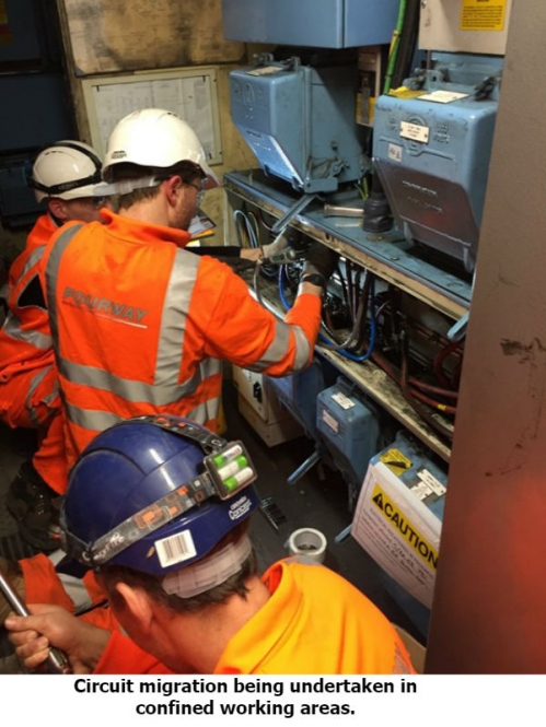
- Confined space in small switch rooms, inverts and tunnels.
- Incomplete record information
Our methodologies and working practises addressed these challenges to deliver a successful outcome, allowing the Link tunnel construction to commence on time.
Migration strategy
Our migration strategy was developed from a detailed understanding of the site arrangements and how they supported the station operation.
Switch Room E7 derived supply from the LUL lighting ring main, dual fed from the two adjacent LUL Sub Stations located at Baker Street and Kilburn. The 2 supply feeds were connected by solid linked fused switches maintaining constant supply at the incoming 800Amp TPN main Bus-bar.
Switch Room E15 was served via switch room E8 at Ticket Hall level, fed via a fused switch down to the OLBI switch room isolator, which in turn fed the OLBI auto bypass switch. The OBLI system served, via the Central Battery Unit, the OLBI Switch Panel DB located within the E7 Switch Room.
A new switch room segregated for LU, DNO & OLBI supplies was constructed on the northbound platform.
The LU supply sub-station feeds were disconnected from the existing switch and drawn back through the ducts to the new switch room, the cables being terminated in a new duplicate panel. This methodology required isolation of the Baker Street supply and retention of the supply from Kilburn. A replacement cable was installed in place of the relocated supply and terminated in the switch vacated by the primary feed, which then allowed energisation of the second feeder switch ensuring restoration of the dual supply.
The basis of OLBI migration was, due to the critical nature of the supply, to provide two operational units. The new system was installed whilst maintaining supply via the existing. A duplicate bypass switch, control and switch gear and central battery were installed and fed from a new supply via E8. This was tested thoroughly. Once operational new sub main cables were installed in preparation for each circuit migration.
Surveys
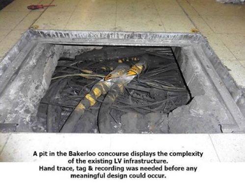
Initially a validation exercise took place including the compilation of records, dimensional backgrounds, CAD and technical data. This was supported by an intrusive ‘Tag and Trace’ survey of all areas. It was crucial a thorough understanding of the infrastructure was gained before commencing design.
Other features of this phase included: -
• Identification, recording and monitoring of existing switch gear, containment routes and associated main, sub main and final circuit cabling within Switch Rooms and platform locations
• Identification of affected communication, 3rd Party / PFI and fire assets within Switch Room and platform locations
• Spatial, capacity and conditional assessments
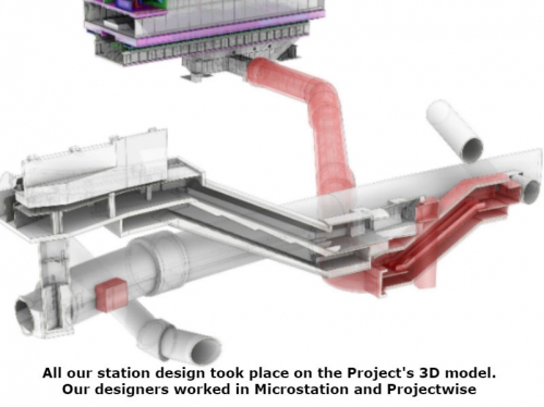
• Clash and impact analysis with the permanent and temporary civil activities, ensuring 3D and 2D model output coordination.
Design
The migration design ensured compliance with the RIBA, CDM and LU 1-538 design criteria. We provided a detailed, constructible, fully coordinated design covering all stages of the works including interim stages, permanent stations works, legacy/new asset interfaces, structural and spatial assessments, clash checking, recoveries etc.
Components of the compliance submission included:
• Survey record information/record correlation
• Detailed design specifications
• External interfaces plan.
• Changeover & isolation strategy
• Cable route sizing requirements
• Discrimination assessment
• Protection assessment (Switch Panels and Distribution Boards)
• Earthing Strategy and Schematics
• Load Assessment
• Cable and Distribution layouts
• Distribution Calculation Model
• System schematics
• 2D & 3D Site layout drawings, showing all assets, orientations
• Equipment, panel layout drawings
• Switch room layout drawings
• Bracket fixing design drawings
• Wiring drawings
• PA, CCTV, PHP design
• Cable & Equipment schedules
• Equipment data sheets
• Changeover & isolation procedures
• Outline delivery programme
During our design process, we paid close attention to any mitigations to the civils programme. Through this we developed an interim migration stage which allowed much of our circuit transfer work to be undertaken in advance of the new switch room completion. This entailed building a temporary switch room close to the location for the new. Circuits were migrated onto this leaving sufficient slack to reach the new location. This reduced the overall critical path and allowed civil works for the new escalator barrel to start significantly earlier.
Implementation
The installation works was carried out over a 9-month period. The main phases were:
1/ Installation of new CMS and cable brackets through the station lower level and adjacent running tunnels.
2/ Installation of sub main cable infrastructure between retained switch rooms and the new switch rooms to facilitate the migration. Approximately 2000m of submain cable was installed on cable tray, platform inverts, escalator machine rooms, on tunnel J-hanger routes and other bracketry at the station.
3/ Preparation and fit-out of a temporary switch room to facility early circuit migration.
4/ Final circuit cabling back from the first point to both the temporary switch cupboard and new switch rooms in preparation for migration activities.
5/ Pre-build: All switch gear was assembled and tested in the off-site environment including client-witnessed Factory Acceptance Testing.
6/ Fit-out of the new switch room including:
• Delivery and installation of Switch gear including critical systems for OLBI and Tunnel Lighting
• Distribution Boards
• Lighting and small power
• Mechanical ventilation
• PAVA speakers
• Fire Alarm System and Fire Dampers
7/ Migration of the incoming LU lighting main for the Bakerloo Line Station. This included jointing 185mm cabling during 3hr engineering hour periods under isolation procedures.
8/ Migration of sub-mains cabling to feed new switch room, including parallel running of old and new. Migration of final circuits.
9/ Decommissioning old switch rooms, including changes to PAVA and Fire System.
Isolation planning
During the design phase, stakeholders, such as station staff and APD were consulted so that our proposals considered the impact to the operation of the station and the resilience of supplies. This included developing, with our civils partners, the requirements for a partial station closure encompassing the Bakerloo Line areas. The isolation strategy was developed to ensure these were the prime considerations. A series of documents were produced from this strategy including a suite of isolation plans which permitted the circuit migrations. Our planner worked with the Costain Skanska JV planners, so these isolations and their relationship with construction works were correctly reflected in the main project programme. Each isolation plan included stage by stage critical go, no-go point gates and fall-back measures. All isolations were co-ordination with Bakerloo Line maintenance team (APD) who we teamed with throughout the planning phase. Our team viewed the strong relationship they had built with APD as a critical ingredient to the success of the project.
Temporary Maintenance
We produced a temporary maintenance strategy to enable us to take possession of the switch rooms. This included a permit to enter systems and a locked-off, tag out procedure to ensure there could be no inadvertent energisation. This critical hazard was tightly controlled by robust process and competent, authorised personnel.
Testing
All testing was carried out by 2391 certificated engineers and verified by our NIEIC Qualified Supervisor.
Assurance and Handover
The handover process was separated into assets transferring to Bakerloo Line Maintenance (APD) and those such as the OLBI which were to be adopted by LU's Power Supply team. The former which applied to most new LV infrastructure used the MAID system. Whereas in the case of the OLBI, the 9 stage QICC process was used.