Piccadilly Line Extension - Tunnel Telephone System
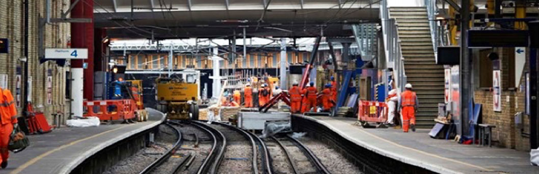
The extension (called PiccEx) consists of a new two-platform station, two sidings where trains can be stabled, approximately 3 km of 4.5m diameter bored tunnels, a ventilation shaft and two escape shafts. The scope of the project included civil works for the two tunnels, track work, the vent shaft, one escape shaft and construction of T5 station. The junction between PiccEx and the existing Heathrow Loop required the tunnels between Terminal 4 and Terminals 123 to be taken out of service until September 2006. The extension opened in 2008.
Tubelines contracted Fourway to deliver a turnkey tunnel telephone system by extending the existing 'Line Normal' system in use on the Piccadilly line. The system engineering carried out by Fourway included production of CDS, RAMS analysis, ergonomic engineering, EMC strategy, standards review, product analysis, failure mode analysis, functional design specification and detailed design. The RIBA C-F design had to address the programme's 3 key output stages which were closure of the Heathrow loop, re-opening the Heathrow loop including newly constructed step-plate junction and opening the Piccadilly line extension to terminal 5.
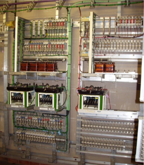
We designed the DC supply interfaces in consultation with the power supply engineers to address the traction current switching & feeding arrangements including the position of rail gaps. We designed new equipment cubicles for either end of the new traction section including connectivity with DC breakers and remote monitoring to line control and SPARCS desks. All telephony circuits were safety critical and designed to the relevant SIL level and included full failure mode analysis. All equipment was fully tested in the factory environment with simulated field conditions before installation. We collaborated with Tubelines maintainers throughout the process.
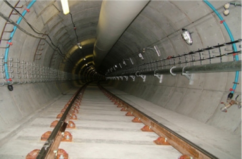
The design for the ‘open wires in tunnel sections required extensive CAD modelling for the new permanent way and rolling stock to suit track clearance and kinematic envelope. Design took into account rail cant, curvature and the effect of carriage throw all of which was surveyed and measured by our own teams. As the open wires were operated from the train cab window we modelled a range of human percentile scenarios to demonstrate 'train operator's reach' remained within the human factors criteria established at outset. This also informed the detailed bracket design process. We manufactured and installed over 10,000 adjustable steel parts to suit the range of tunnel environments. Final bracket assemblies were vibration tested to accord with relevant RIA standards. All installation was carried out from on-track plant co-ordinated through the track access planning regime. To support final inspection we designed and built our own track gauges and trained staff to use them.
TT wire was installed using our own certificated on-track plant designed to decoil and straighten TT wire on the move. TT wire tensioning and making off was subject to a bespoke set of tests to simulate use by train operators in emergency conditions.
We designed and implemented all works required within the Piccadilly line control room. This included wiring throughout the Interlocking Machine Room and modification of the control room desks situated above to accept the additional switches and circuits. All modifications were the subject of operator task studies and mocked-up in full before implementation. All work was carried out under planned equipment possessions with hand back procedures to enter modified systems into operational service.
At each stage of the programme we collaborated with power supply engineers to carry out integrated testing as the new DC supply arrangements were brought into use.