East London Line Tunnel Telephone System
During a 3 year closure of the East London Line (ELL) Fourway replaced the 1950s 'Line Normal' tunnel telephone system. The primary reasons for the replacement was life expiry. Additional more specific reasons included:
- Migration of TT control facilities from Baker Street (Met Line) to New Cross Depot to facilitate changes in ELL ownership.
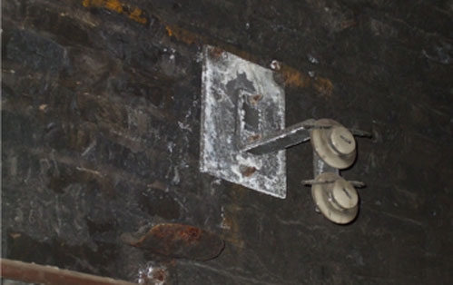
- Water ingress throughout the tunnel section leading to severe corrosion of the open wires and brackets.
- The existing central equipment at Surrey Docks & Whitechapel subs was intolerant to moisture levels in the ELL tunnel sections.
System Engineering
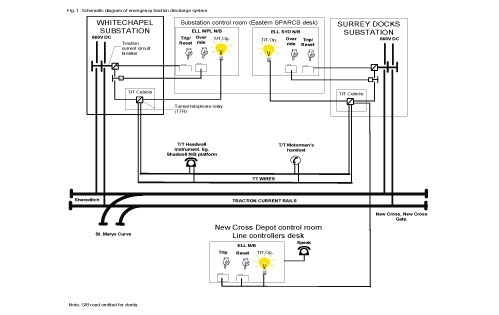
We developed a turnkey system consisting of two TT cubicles. One located in each substation. Each contained relays (TTRs) which controlled the DC traction current circuit breakers. We designed the system such that when it was operated the traction current breakers at both Whitechapel and Surrey Docks tripped thus removing current from the section.
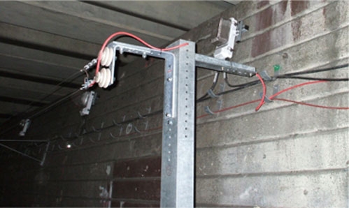
Connection between the cubicles was achieved by two separate pairs of wires (one pair for each road). In stations this was a 2 core MICC cable passing from headwall to tailwall in the invert, cable run or clipped to the platform edge. In tunnels the pair changes to two bare copper-cadmium wires (known as TT wires).
A new operator's panel located at New Cross Depot control room provided trip, reset control and indications. We designed all DC supply interfaces in consultation with the power supply engineers including connections to the Eastern SPARCS desk located in the power supply control room in central London.
The system design submission was the culmination of consultation with maintainer's and chief engineer’s departments.
Procurement
Fourway engaged equipment manufacturer Ford Electronics to provide the cubicles and control panel.
Design
The brackets required complete replacement due to corrosion and changes in Pway alignment. The design for these took into account rail cant, curvature and the effect of carriage throw all of which were surveyed and measured by our teams. As the open wires were operated from the train cab window we modelled a range of human percentile scenarios to demonstrate the 'train operator's reach' remained within the human factors criteria established at outset. This also informed the detailed bracket design process. A further complexity was addressing the risk of designing to fix into degraded 150 year old Victorian brick tunnel structures.
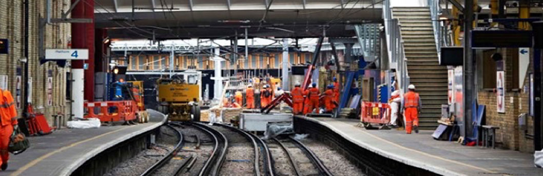
Installation
All installation was carried out from our own on-track plant developed at Cheshunt. Our teams coordinated the site face with multiple trades through the track access planning regime. A 2000m control cable was laid in J hangers between surrey docks and new cross depot control room.
Testing
The rigour of inspection and testing accorded with the standards for an operational telecomms system. Each item of equipment was bench examined, each wire crimp was tested, speech paths were cross talk tested, fixings were pull-tested, TT wire was tension tested, bracket assemblies were vibration tested etc. To support final inspection of the installed TT brackets, we designed and built our own track gauges and trained staff to use them. These were used to sign off track clearance certification.
All central equipment was tested in the factory environment fully simulating field conditions. Final acceptance testing was integrated with the Power Supply Engineer's live DC traction supplies. We decommissioned control and monitoring circuits at Baker Street line control room. We decommissioned the line normal equipment at Whitechapel and Surrey Docks substations. All work on operational assets was conducted under safety AWC in accordance with LU licensing procedures.
Handover
We provided test and inspection data and O & M manuals. The final stages of testing were completed with LU maintainers in attendance. In particular the stability of the TT system shunt in wet conditions was critical to successful handover.