White City Tunnel Telephone
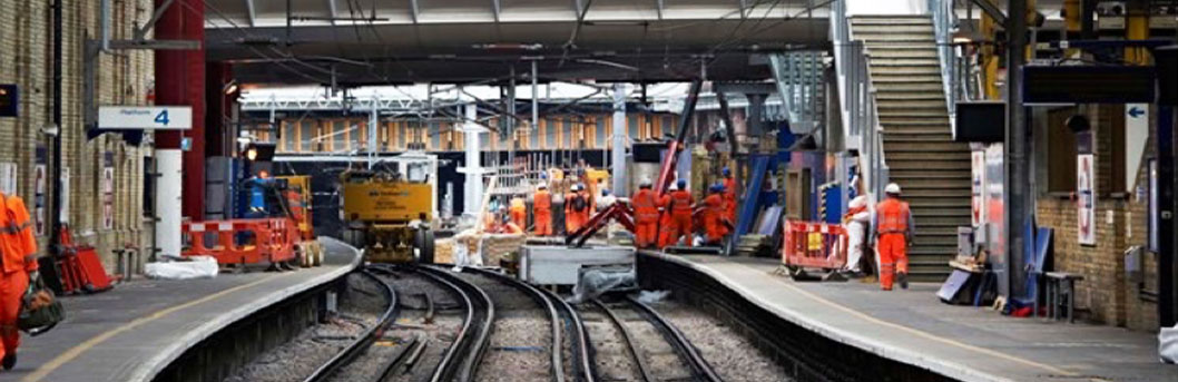
LU redeveloped approximately 40 acres of land at White City in West London incorporating the following elements: New Central Line sidings including staff accommodation; Removal of Wood Lane Station; Overbuilding two East and West bound sections of the Central Line; Alterations to the Hammersmith and City Line Viaduct (Wood Lane bridge); Refurbishment of former DIMCO building to form part of bus station and location for LUL substation and or CHP plant; Construction of a new station on Wood Lane.
For this project Fourway provided Metronet tunnel telephone engineering and delivery services. We were engaged for feasibility, design, construction, bring into use and handover. Our expertise in legacy LU tunnel telephone systems was a key factor for the engagement.
Feasibility
Two areas of impact were considered: Did changes to the built environment effect LU’s obligation to provide Tunnel Telephone ie were the legislative requirements still met? And secondly did these changes impact the existing Central Line tunnel telephone system?
Fourway were engaged to assess feasibility. The construction design and phasing indicated 3 areas of impact (i) overbuilding sections of open Central Line would require extension of TT open wire system (ii) relocating White City sidings underground would require a new TT system to control the traction section for new sidings. (iii) Relocation of the existing Wood Lane Substation tunnel telephone room would require the migration of existing TT equipment (affecting Notting Hill Gate Section to Wood Lane and Wood Lane to Park Royal Section).
During the feasibility stage we undertook extensive consultation with stakeholders such as the system maintainers, asset engineers, chief engineers and duty operations managers. A key part of the feasibility was determining the best assurance strategy that is the easiest route to approval in principle and thus reduce overall project risk.
System Engineering
For (iii) the existing TT equipment migration, we captured and reviewed a range of source data including the Substation test and commissioning plan, Project programme including commissioning dates and proposed possession arrangements, New Substation floor layout plans; New substation electrical drawings (ie Traction supply arrangements, earthing arrangements, main and back-up power supply sources.); Sources of new or spare TT central equipment; Cable route drawings for both new and old substations; Tunnel Telephone book wiring drawings for Park Royal/Wood Lane/Notting Hill Gate circuits including 10b Wood Lane; maintenance data on condition of existing TT central equipment; Applicable LU CED standards.
We developed a migration strategy based around the philosophy of deploying a training unit held by the maintainer. We prepared a schedule of factory tests to confirm the unit was both complete and capable of being integrated into the operational system. We prepared a series of detailed phase drawings including materials & components, cable installation, interfacing junction points and the stage testing required to assure the risk to the operational railway was as low as reasonably practical. The installation was undertaken by the maintainer.
For (ii) the sidings approach road TT system the preference was for two identical TT equipment racks located at DC switch 1088 and DC switch 1084 based on re-engineering Westinghouse equipment previously developed for the Central Line Project. From an assurance perspective this option had the advantage of relying heavily on the principles of previously adopted designs. The majority of materials, components, functionality and performance had been previously tried and tested. There were some instances of component obsolescence where replacements were justified by appropriate studies and analysis. Other important aspects of system compliance we considered were risk of wrong side failure, trip time and system reliability.
Design
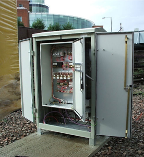
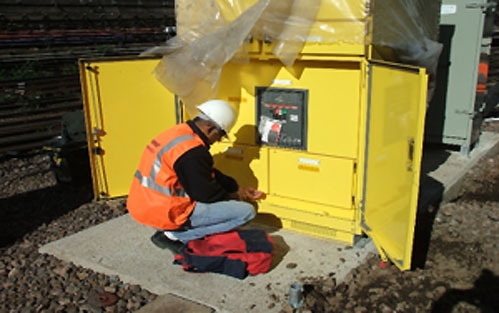
The single option selected: Individual racks housing single TTRs located as near as practical to the associated DC switch to reduce the risk of wrong side failure. As no buildings existed in these locations weather-proof, environmental cabinets were selected to house the equipment. These needed to be as easy as possible to access and not in themselves a trackside obstruction. The control panel which contained the trip and reset functions was located in the Duty Depot Manager’s Office within White City Station.
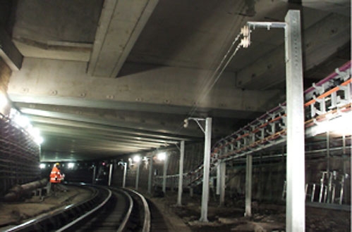
The traction section was a single road approximately 400m long of which 200m was overbuilt necessitating TT wires. We designed a bracket support system that complied with rolling stock clearances and met train driver human factors requirements.
Installation and testing
The installation was carried out in both engineering hours and weekend possessions. All trackside installations were gauged to ensure they met the requirements of track clearance. The TT wires were the subject of ‘pinch testing’ which is a method of establishing the tension of the wires is in accordance with pre-agreed limits derived from HF assessment.
A regime of progressive testing was adopted. Initially all materials and components were individually. The main equipment racks and control panel were separately bench tested and then factory acceptance tested with full simulation of field conditions. Site acceptance testing was conducted with Metronet and the system maintainers to ensure smooth transition of the system into maintenance. DC integration testing was carried out by a combined team of power supply engineers and Fourway testers.
Once operational, all work on the TT system was carried out under AWC procedures by licensed testers.