Piccadilly Line Extension - Signal Post Telephone System
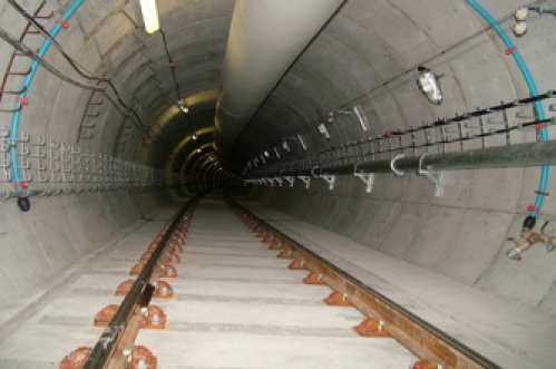
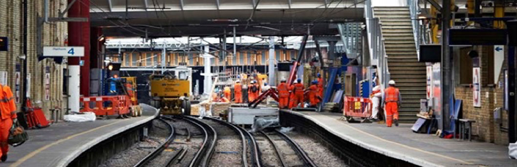
The extension (called PiccEx) consists of a new two-platform station, two sidings where trains can be stabled, approximately 3 km of 4.5m diameter bored tunnels, a ventilation shaft and two escape shafts. The scope of the project included civil works for the two tunnels, track work, the vent shaft, one escape shaft and construction of T5 station. The junction between PiccEx and the existing Heathrow Loop required the tunnels between Terminal 4 and Terminals 123 to be taken out of service until September 2006. The extension opened in 2008.
Tubelines contracted Fourway to provide a turnkey signal post telephone system for PiccEx. The RIBA C-F design had to address the programme's 3 key output stages which were closure of the Heathrow loop, re-opening the Heathrow loop including newly constructed step-plate junction and opening the Piccadilly line extension to terminal 5. Our scope required us to analyse the changes in train operations and deliver a series of telephony modifications for the programme. For stage 1 the existing system was partially decommissioned to reflect the reduced service in the area of the Heathrow loop. The stage 2 design introduced a new 32 line concentrator located in the IMR at Terminal 123 Station. Our design defined the system equipment and cabling requirements for networking with the existing Piccadilly line SPT system. The system engineering carried out by Fourway included production of CDS, RAMS analysis, ergonomic engineering, EMC strategy, standards review, product analysis, failure mode analysis, functional design specification and detailed design. We involved Tubelines maintainers throughout the process ensuring they agreed with all the engineering decisions.
During detailed design we defined mains power arrangements, cable routing, product and materials selection. This included the copper circuit infrastructure involving several large MDF frames and a network of local smaller frames to serve the individual SPTs and come-to telephone signs.
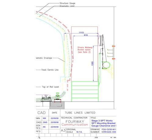
Where telephones were located in the tunnel sections we undertook extensive CAD modelling of the new permanent way and rolling stock to suit track clearance and kinematic envelope. Design took into account rail cant, curvature and the effect of car throw all of which was surveyed and measured by our own teams. As the SPTs were operated from the train cab window we modelled a range of human percentile scenarios to demonstrate 'train operator's reach' remained within the human factors criteria established at outset. This also informed the detailed bracket design process. We manufactured and installed over 2000 adjustable steel parts to suit the range of tunnel environments. Final bracket assemblies were vibration tested to accord with relevant RIA standards. All installation was carried out from on-track plant co-ordinated through the track access planning regime. To support final inspection we designed and built our own track structure gauges and trained staff to use them.
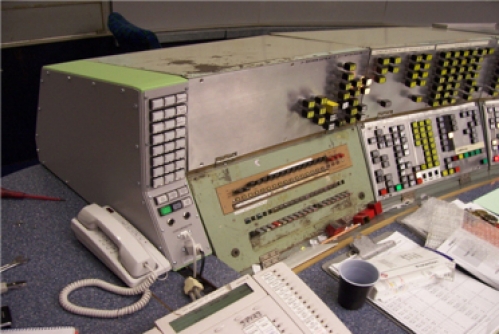
Control Room
The most critical area was live changeover which introduced a new control panel to the 1960s desks located in the Piccadilly Line control room at Earls Court. The design incorporated a staged approach defining incremental testing, contingency and fall back measures. This included a programme of off-site pretesting with fully simulated field conditions. The new panel was successfully changed over in one engineering shift without any impact on the operation of the railway. In the lead up to stage 3 approximately 30 additional phones were sequentially added to the live system. All activity was carried out under LU 'Authority to Work' procedures.